Tag: university

Concrete manufacture and testing

Concrete manufacture and testing

I observed the testing of concrete intended for the headhouses of London Power Tunnels 2. This took place at the batching plant Capital Concrete in east London.

There are two types of concrete batching: wet mixes and dry mixes. The former can generally produce a higher quality concrete because it can be mixed using the industrial-scale mixers at the batching plant, rather than smaller mixers available on construction sites. Today, a wet mix is being prepared for the concrete slab. The intended strength is C40/50 (meaning a failure strength of 50MPa on a 5cm x 5cm x 5cm cube).

Note on sustainability. Concrete production is one of the world’s largest sources of CO2 pollution, meaning civil engineers need to come up with alternatives which are less polluting. In normal concrete, which is based on Portland cement, about 1000kg of CO2 is produced per tonne of concrete. A new technology called Earth Friendly Concrete (EFC) is capable of reducing this to about 200kg CO2 per tonne of concrete – a significant improvement – by replacing the Portland cement with Ground Granualted Blast Furnace Slag (GGBS) and waste fly ash from industry. The concept is in its infancy so its properties can be unpredictable – previous batches have not reached the required strength because of low-quality fly ash supplied from Dunkirk in France; now that the supplier has been changed, today’s mix should pass the required tests. If the rollout of EFC on this large project is successful, it could be a significant turning point for the construction industry to reduce its emmisions from concrete production.

The batch for testing is a sacrificial batch – it will not be sent directly to the project, but if test mix passes the strength tests, the same mix will be used on the project.

Layout of the plant:

  • Silos storing cement (or Earth Friendly cement alternative)
  • Aggregate storage area
  • Huge industrial concrete mixer, with a ‘tap’ to transfer the mix straigh into mixing lorries for transport to site
^ The giant, industrial concrete mixer at the batching plant.

Testing the batch:

1) Slump test. This is done every half an hour for three hours. Concrete is filled into a conical mould and then the mould is removed so the mixture spreads into a heap. The change in height of the heap is the slump.

2) Bleed test. A cyclindrical container is filled with the concrete mix in five layers – between each layer a vibrating tool is used to ‘tamp’ the mixture and reduce air bubbles. In general, the way the concrete firms up is based on the water separating from the heavier particles over time until enough stiffness is achieved. The amount of water that forms at the top of the cylinder is the bleed; a lid prevents evaporated water from escaping from the test. The use of high proportions of GGBS results in a longer bleed time that conventional concrete but this can be reduced with fine aggregates (<50 micrometres). When bleed occurs on site, either the bleed water is remixed into the concrete (which may result in a weak top surface) or one can wait for the bleed water to evaporate. If the rate of evaporation is faster than the rate of bleed (e.g. on a very hot day), the concrete may experience plastic shrinkage, which is undesirable and should be avoided.

3) Cube tests. 5cm cubes are filled with the mix. They are tested, usually with a hydraulic machine, on days 1-7, day 14, 28, 56 and 96 for failure strength. Concrete gets stronger over time and the 28-day strength is usually the quoted value; the material must reach its target strength (here, 50 MPa) by that date to be acceptable.

4) Weight test. This is just a way of obtaining the concrete density, which is a vital parameter to consider for safe structural concrete design.

5) Beam test. A 3-point test (simple supports at the ends, and a point force applied at the middle) is taken on an unreinforced beam of concrete at 28 days. This tests the bending strength of the mix.

Rhodes House renovation – site tour, Oxford

Rhodes House renovation – site tour, Oxford

Rhodes House is a university building in the centre of Oxford, home to postgraduates on a type of scholarship. It contains residential areas as well as conference and teaching and learning spaces. Despite the building being less than 100 years old, its style is more historic, with a design by Sir Herbert Baker which is reminiscent of 1600s Europe – to match much of the city’s university architecture.

As a listed building, it’s vital that the architecture is well-preserved. The idea of the project was, as a lead engineer described, to make it appear as if nothing had changed once the project is complete: most of the updates will be made underground, including a new conference room and new accessible lifts.

The tasks:

1. Install a spiral staircase into the rotunda

This is the rotunda from the basement. The celing must be drilled to form a hole leading to the ground floor, in which the staircase will be installed. The other challenge is the removal of the support columns – the weight they are currently carrying is minimal but the remaining concrete must be strong enough to hold as a kind of cantilever from the outer walls. Calculations predict that reinforcements will not be required, but this could change as the project progresses.

2. Preserve the strong masonry columns in the basement as a structural component, and line them up with those on the floors above

The original columns are extremely robust and strong so will continue to be used to hold the basement structure up. They will be refined and re-covered for aesthetic appeal.

3. Extend the basement: to create a large conference space and fire exits

The basement is extended using exposed reinforced concrete. There has been specially selected insulation installed for heat regulation; the holes you can see link to the ventilation and air conditioning system. The arch is an effective support structure; it also provides natural lighting for the conference space.

4. Construct sixteen new residential rooms in an excavated space, whilst allowing natural light in.

The rooms are dug underground. As well as being a space-saving solution, this is excellent for energy efficiency because the earth covering the rooms is a thick insulator, keeping rooms cool in the summer and warm in the winter. Spaces are fronted with solid oak doors and triple-glazed, full length windows; the walkway will be lined with trees down the middle to provide privacy.

5. Create a new outdoor social area

Above is the space where the social area will be – clearly, there is still work to do! On the left is a diagram of the small cafe structure, which will be used during events and conferences. I drew it out to try and visualise what had been explained by the lead engineer. Essentially a process called steam-bending will form timber into the right shape. This material takes the weight of the structure, which will be about four metres high. Weatherproof structural glass will be arranged in a facade around the edge, taking no weight but providing shelter from the weather on rainy, windy or cold days.

Hungerford rail and footbridges, London

Hungerford rail and footbridges, London

The current bridge at Hungerford is formed of two elements: a trussed beam railway bridge on heavy brick supports completed in 1870, and either side of that, two lightweight Golden Jubilee footbridges. These were added in 2003 and are engineered to be attached to the original structure as well as supporting their own weight via a cable-stayed system. The bridge’s history and the cleverness of the engineers to produce something of such elegance and effectivness makes this my favourite bridge in London.

The hardest part about designed the new footbridges is that of course, they need to fit with what is already there. The steel cables and beams of the new bridges are attached to the solid foundations of the old rail rail bridge via a solid ring and carefully calculated pin joints – sketched above. I think it’s clear that the weight of the new bridges is almost negligible compared to the old – partly because pedestrians are much lighter and produce much less vibration than trains, but also signifying massive advancements in materials and engineering technology since the 19th century.

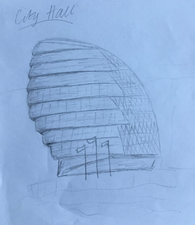
City Hall, London

City Hall, London

City Hall is an understated yet impactful building on the riverside in London. It is the headquarters of the Mayor of London and Greater London Authority – where decisions are made with regards to transport and other issues in the city. It was completed in 2002 and its ten stories each offer views towards the river.

This has always been one of my favourite modern buildings in London, because its shape is understated; it’s not overwhelming yet the building’s presence is somehow fitting to its location and function.

Although my sketch can’t depict it, the inside features a spiralling ramp that circles the building, framing the main assembly hall on the ground floor. Light pours in through the river-facing glass panelling providing a professional yet inviting atmosphere. Somehow, I just find this building intriguing!

Fernsehturm, Munich

Fernsehturm, Munich

Munich’s 291m Fernsehturm, or TV Tower, is an iconic part of its skyline. Being lucky enough to visit, I sketched its shape to show its structure and how each section is used.

A year ago, I also visited Berlin, the largest city in Germany and also home to an iconic TV Tower. Well I was interested in comparing these two structures, which have similar functions yet differing shapes and histories.

The Berlin tower is the tallest structure in Germany, at 318m (compared to the 291m of Munich’s tower). Much of each tower’s total height is made from its top aerial, coloured red and white. Berlin’s is tapered; Munich’s is a straight cylinder. Also, a lightly tapered concrete base contains the lifts in each tower.

Both contain two public floors: one for views and the other a revolving restaurant. Munich’s restaurant is at 182m and viewing floor at 190m; Berlin’s restaurant is at 207m and viewing floor at 203m, towards the bottom of the iconic 32m diameter sphere. Its triangular embossed facade also adds to the impact of the panoramic views of the city.

The Munich tower was completed in 1968, the Berlin tower in 1969. Incredibly, at the time, they were in different countries, the BRD (West Germany) and the GDR (East Germany).

BMW Welt, Munich

BMW Welt, Munich

BMW Welt, or BMW World, is a centre and museum in Munich showcases the history and future of the automobile industry. The building is modern and futuristic. To access it, you walk over a bridge over the main road, leading you straight through the entrance to the first floor.

It was from the bridge I sketched; facing the geometric hourglass shape that is the centrepiece of the building’s design.

My close up photo of the steel truss frame my sketch also conveys. It’s clear the truss is useful to increase the twisted structure’s rigidity.

Bridge in Rouen, France

Bridge in Rouen, France

A road trip to Rouen, northern France a while ago led me to this engineering marvel over the Seine: Pont Gustave-Flaubert. It’s actually an opening bridge, which I didn’t even realise whilst I was there. I sketched it here from a photograph I took myself.

It’s a cable-stayed bridge, meaning its weight is carried to the support via cables that connect it to the concrete towers. In fact, the cables wrap around pulleys, which allow for some movement of the structure, but thereby reducing the chance of fracture.

The cables transfer the weight on the bridge on to the reinforced concrete towers and thereby into the ground, producing a structurally stable and reliable yet lightweight bridge.

From inspection I imagine the platforms to be semi-rigid – anchored to the ground but with a pontoon-type floating top element, although this assumption is not confirmed.

Clifton Suspension Bridge, Bristol

Clifton Suspension Bridge, Bristol

Another university open day brought me to Bristol. I found a nice spot a little out of town to get my sketchbook out and admire this feat of Victorian engineering.

The suspension bridge spans over the river Avon and contains two distinctive stone towers sitting on either side of the gorge. Steel cables connect them to each other and support the extended span of road. It was definitely a breathtaking view!

Winter Garden, Sheffield

Winter Garden, Sheffield

I visited Sheffield for a university offer day. I explored the city a bit before my train home, coming across this building, the ‘Winter Garden’.

The idea of the building is to act as a temperate greenhouse, where elements of the environment such as moisture and temperature can be carefully monitored, allowing 2,000 plant species to thrive. It is the largest of its urban kind in Europe.

The shape of the building is interesting because the glass ceiling uses a suspension system. Three ‘shells’ in the shape of quadratic curves sit inside each other, and are anchored to the ground at either end. This allows for a very lightweight structure. In fact, the building uses very little concrete and is instead mainly formed of timber arches, a steel frame and glass panelling.

Sky Garden, London (20 Fenchurch St)

Sky Garden, London (20 Fenchurch St)

Otherwise known as the Walkie Talkie, this skyscraper at 20 Fenchurch Street features a restaurant more than 100m in the air. The elegant shape of the windows gives way to some of the best views in London.

I’ve sketched the building from a few angles to try and give the shape justice. There is a balcony just outside the curved window area.

This is the picture I took while I was at the Sky Garden. As you can see, the views over the city, the Thames and its bridges are spectacular. The building uses steel framing and strong glass panelling to achieve this.