Category: ALL BLOG POSTS

Big Ben (Clock Tower) model

Big Ben (Clock Tower) model

Probably the most iconic landmark in London, Big Ben was completed in 1869. Technically the name referes to the actual bell inside, but is normally assossiated with the actual tower. It began renovations in 2017 and was covered in scaffolding for years, destroying what is my favourite view of the building: stepping out of the western exit of Westminster tube station, it comes out of nowhere but stands so boldly and beautifully that you can’t seem to look away.

I tried to capture some of the detail in my model. The shape isn’t hugely complex, especially since there are no difficult curves. I split the form up into sections and created nets for each. Then added small details with tiny strips of paper. The clock itself was not easy to replicate, but I practised a couple of times and then used a black fineliner pen to draw in on white card.

Rhodes House renovation – site tour, Oxford

Rhodes House renovation – site tour, Oxford

Rhodes House is a university building in the centre of Oxford, home to postgraduates on a type of scholarship. It contains residential areas as well as conference and teaching and learning spaces. Despite the building being less than 100 years old, its style is more historic, with a design by Sir Herbert Baker which is reminiscent of 1600s Europe – to match much of the city’s university architecture.

As a listed building, it’s vital that the architecture is well-preserved. The idea of the project was, as a lead engineer described, to make it appear as if nothing had changed once the project is complete: most of the updates will be made underground, including a new conference room and new accessible lifts.

The tasks:

1. Install a spiral staircase into the rotunda

This is the rotunda from the basement. The celing must be drilled to form a hole leading to the ground floor, in which the staircase will be installed. The other challenge is the removal of the support columns – the weight they are currently carrying is minimal but the remaining concrete must be strong enough to hold as a kind of cantilever from the outer walls. Calculations predict that reinforcements will not be required, but this could change as the project progresses.

2. Preserve the strong masonry columns in the basement as a structural component, and line them up with those on the floors above

The original columns are extremely robust and strong so will continue to be used to hold the basement structure up. They will be refined and re-covered for aesthetic appeal.

3. Extend the basement: to create a large conference space and fire exits

The basement is extended using exposed reinforced concrete. There has been specially selected insulation installed for heat regulation; the holes you can see link to the ventilation and air conditioning system. The arch is an effective support structure; it also provides natural lighting for the conference space.

4. Construct sixteen new residential rooms in an excavated space, whilst allowing natural light in.

The rooms are dug underground. As well as being a space-saving solution, this is excellent for energy efficiency because the earth covering the rooms is a thick insulator, keeping rooms cool in the summer and warm in the winter. Spaces are fronted with solid oak doors and triple-glazed, full length windows; the walkway will be lined with trees down the middle to provide privacy.

5. Create a new outdoor social area

Above is the space where the social area will be – clearly, there is still work to do! On the left is a diagram of the small cafe structure, which will be used during events and conferences. I drew it out to try and visualise what had been explained by the lead engineer. Essentially a process called steam-bending will form timber into the right shape. This material takes the weight of the structure, which will be about four metres high. Weatherproof structural glass will be arranged in a facade around the edge, taking no weight but providing shelter from the weather on rainy, windy or cold days.

A journey in Icelandic churches: photo essay

A journey in Icelandic churches: photo essay

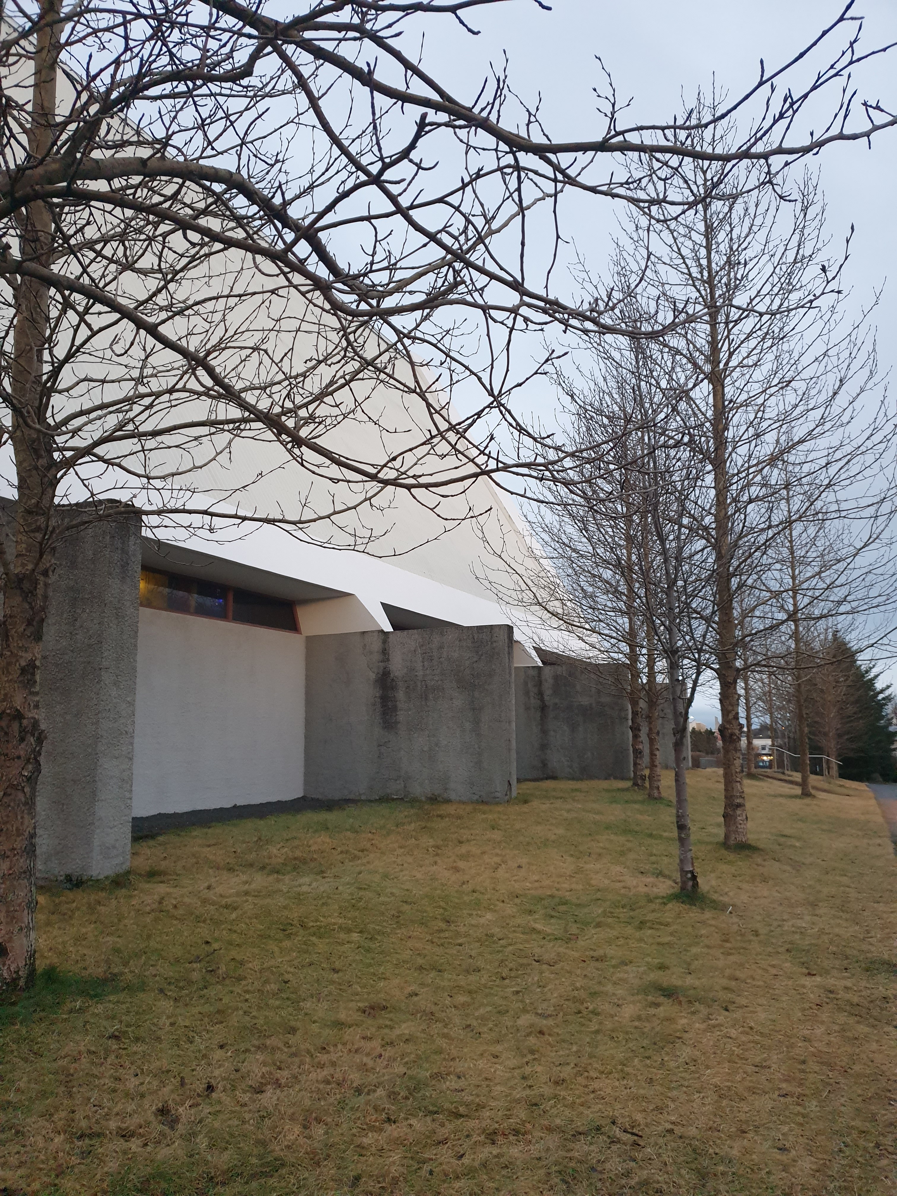
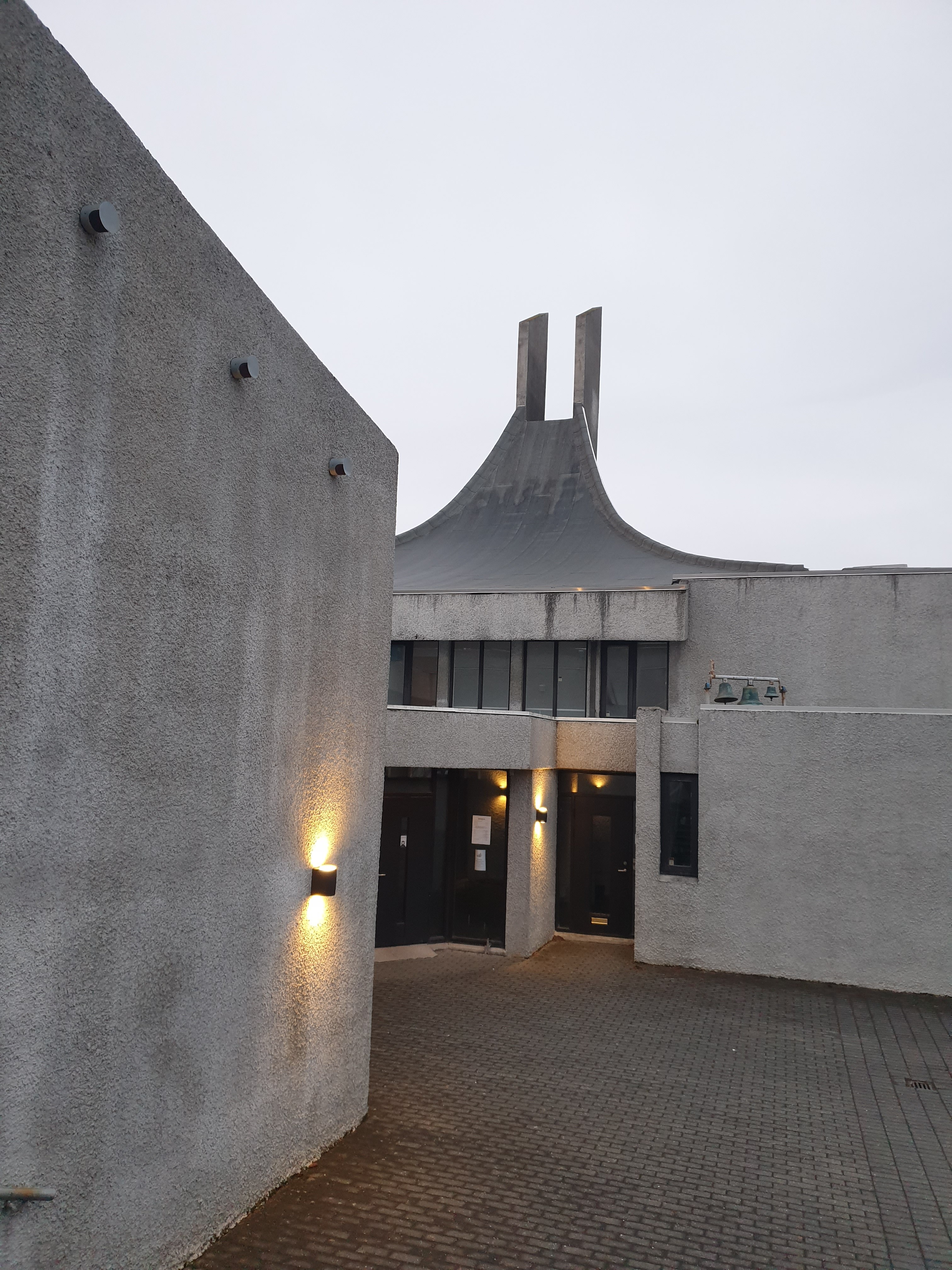
Wandering around Keflavik, the airport town of Reykjavik, Iceland, with the arctic wind whipping in my face and the sound of crashing waves behind me in the darkness, I came across an eerie, towering white building, like an huge spike amidst the squat shops and houses in the town. I walked closer – it was a church. I walked around it: gigantic white arms stuck out from the main building into the park and the place was lit up by purple light. I found it very mystifying and beautiful.

The reason I was taken aback by such a building was that it was so unexpected. I thought nordic Iceland would have almost exclusively traditional, cosy-looking churches, especially in a town other than the capital. Here’s the church:

Ytri-Njarðvíkurkirkja

On further research, I found out there are lots of unique churches in both Keflavik, as well as in Reykjavik. I made a note of the ones I wanted to see. A guide book explained that often, Icelandic architects-in-training had to go to another country to study before an architecture school was established in such a small nation. When these people returned home from Denmark, Germany, Italy, the US and more, Iceland became a melting pot of styles and influences, therefore producing a number of unique buildings.

The other point is that Icelanders are very in-touch with nature, and their buildings reflect that. (Reykjavik, although housing more than half the country’s population, is not a large city, so you’re never far from the countryside.) Often, the churches stick up out of the ground mimicking the mountains, rockfalls, volcanoes and waterfalls of the natural landscape of the country.

I put together a little church tour in Reykjavik and Keflavik, and this photo series shows those I explored.

Keflavíkurkirkja

Reykjavik Cathedral

Langholtskirkja

Askirkja

Laugarneskirkja

Kirkja óháða safnaðarins

Hateigskirkja

Hallgrimskirkja

Frikirkjan i Reykjavik

Landakotskirja

Seltjarneskirja

The churches definitely cover a huge range of styles and designs,. I enjoyed the beauty of each one. Some key points to note that unite them, though:

  • Lack of glass, especially as other European churches often indulge in large stained glass windows. This may be related to Iceland’s climate – glass is not a very good insulator, and can also be fragile, which makes it difficult to protect against blizzards.
  • Concrete designs that take inspiration from the surrounding landscape – huge towering rocks and vast sea
  • Use of corrugated iron. In most other countries, this material is used exclusively for non-aesthetic purposes, such as for industrial buildings or warehouses. Yet here its strength against the wind, rain, snow and ice has been embraced by Icelandic architects and engineers to their advantage (the ridges are placed vertically so that water runs off).
LPT2: more TBM insight

LPT2: more TBM insight

As the project progresses, the length of the tunnel increases and there is more space to walk along the inside of the TBM to complete various jobs. Currently, about 70m of tunnel has been excavated. Inside, it looks like a long, slightly mucky corridor:

When you reach the cabin and boring head, it gets more interesting. In general whilst drilling is taking place, two workers are required in this area.

  1. TBM driver. They sit in the small cabin and steer the path of the TBM and mechanical arms via various levers and buttons. They can see what is happening at the very front via a screen connected to a camera.
  2. Someone to watch the placement of the concrete rings. They stand in front of the cabin, where the rings are transferred through, and instruct the TBM driver where the next ring must be placed through a microphone. This can be as simple as, for example, ‘left a bit, down, stop’.

Each concrete ring weighs about a tonne and is approximately 1.2m long.

LPT2: use of TBMs

LPT2: use of TBMs

Use of a TBM, or tunnel boring machine, is essential to the success of such large-scale, 21st century tunnelling projects. Interestingly, they are a relatively new technology and hand-mining techniques were still in use for tunnel excavations in the UK in the last 50 years.

The machine consists of gantries, or functional sections (which can include electrical gantries, motor gantries and more), and can total 200m in length. This results in one major problem: how can the machine be used before enough tunnel length has been bored for it to even fit in?

  • The solution is that only one gantry needs to begin in the shaft. The rest remain on the surface, but are connected to the first via a series of ‘umbilical cords’ running down the shaft wall. As drilling progresses, more gantries can be inserted into the tunnel using a crane lift.
^ the structure of the TBM and the two shafts at New Cross can be seen in my sketch here. At this level of progression, only the western TBM has been inserted, with much of it still sitting above ground

The final length of the TBM is about 400m. Once the western TBM is fully inserted, the eastern one will begin a similar process. We are drilling in both directions because this site is the midpoint of the project.

The TBMs are given names; a bit like ships, they tend to be female. Ours above has been named Edith!

LPT2: high voltage power cable structure

LPT2: high voltage power cable structure

^ diagram of cable cross section

These thick cables are about 150mm in diameter and carry a high-voltage current way down the power tunnels that extend through south London. They are similar in design to those carried by power lines that stretch across the countryside. High voltage, but low current, results in minimal power loss and overheating.

Six cables run through the tunnel, as part of two circuit systems.

The total tunnelling length is about 32km, which means about 200km of cables must be installed during the project. This requires heavy lifting machinery, with the cables weighing about 50kg per metre.

Installation of cables will be via a monorail that runs along the tunnel ceiling.

LPT2: more on reinforced concrete

LPT2: more on reinforced concrete

The tunnels at London Power Tunnels 2 use a spray of reinforced concrete to stabilise the lining whilst thick concrete rings are inserted.

The material chosen consists of cement, sand, and steel fibre reinforcements. . I imagined these to be thin and easily bent, but on inspection of the sprayed wall in the tunnel I saw they were firm: of about 1mm diameter, hard and spiky. Although you might expect the spray to form a smooth-ish façade on the inside of the tunnel, in fact it is very rough-looking, with spikes of steel fibre.

^^ the fibre-reinforced concrete façade; you can see the size of the steel fibres against my hand

LPT2: vertical shaft construction

LPT2: vertical shaft construction

Before the deep, horizontal tunnels can be constructed, the project needs stable shafts, which look like vertical tunnels and are about 12m in diameter. From the bottom of these, horizontal tunnelling will then begin. Formation of the vertical shafts consists of this process:

  1. Secant piling to cut off groundwater
  • Secant piles consist of reinforced concrete column foundations that interlock, driven into the ground. They have a greater stiffness than traditional sheet piles, and are essential when such a high water table is involved. These form a concrete ‘wall’ around the vertical shaft for the top half of its vertical height
  • The piles consist of harder, reinforced concrete ‘male’ piles, and softer, unreinforced concrete ‘female’ piles
  • Secant piles form a temporary support while shaft underpinning takes place

2. Shaft underpinning

This technique works ring by ring. About 1m deep, a circular section is excavated with machinery. Segment rings of the same 1m height can then be inserted. Then they are stabilised by filling behind them with grout. This is a course, cement-like substance that is pumped behind the ring via groutholes designed specifically for this purpose.

At each excavation, the first and last rings to be inserted are angled, to enable the last ring to slide in.

The process continues to build about one ring a day until the shaft is completed.

3. Contiguous bored piling

Approximately one third of the way down the shaft, about 15m deep, the type of piles used changes. Contiguous bored piles are similar to secant piles, but the previous ‘female’ piles are replaced by grout fill instead. This is a because the ground changes from ‘made (build-upon) ground’ and Thanet sand to mostly chalk, which is firm enough to hold its shape with this new piling, and we pass the water table.

^ diagram of pile structure as we travel down the shaft

LPT2 horizontal tunnel construction: an explanation

LPT2 horizontal tunnel construction: an explanation

At the London Power Tunnels 2 site at New Cross, the primary rock type is chalk. This rock has desirable properties for tunnelling, since it tends to be very stable. However, issues arrive when the rock is weathered and/or fractured:

  • The existence of fractures, or gaps in the rock, increases its permeability; it becomes more likely to crumble and absorb water.
  • This effect is exacerbated at depth, which is a particular problem here, where we’re working at depths of between 40 and 60m below ground level.
  • Central London has a high water table – the Thames is never far away
  • It’s important then to both fill the gaps in the rock and pump water away accordingly to ensure tunnel stability.

The horizontal tunnel construction begins with the digging and stabilisation of a vertical shaft. It is stabilised and then construction of the horizontal tunnels can begin. According to the properties of the site just established, the method of horizontal drilling (after the digging of the shafts) is this:

1. Saw-cut the initial frame of the tunnel from the bottom of the shaft.

  • Segments of rock and the concrete shaft wall get broken away ready to grout behind the newly-formed gap

2. Fissure grouting

  • Fractures in the rock get filled with a grout to block pores, decreasing the material’s permeability around the perimeter of the shafts

4. Construct the horizontal shaft

  • The excavation consists of step-by-step ‘advances’ using a ‘Blue Badger’ excavator machine. This creates a hole (of depth a few metres) with curved sides, a stable shape.

5. Fore/back-shunt using SCL

  • At each advance, the section is stabilised with fast setting concrete. This is applied with a spray-concrete lining (SCL) process, using a sprayer machine called the MEYCO Oruga, which runs along tracks in the shaft.

London Power Tunnels 2 (LPT2), New Cross site

London Power Tunnels 2 (LPT2), New Cross site

An internship with an engineering company allowed me to be a part of this vital project. Following on from London Power Tunnels 1, which spanned north London, these new pipes will connect the dots of south London, replacing old oil-filled pipes in a decaying power network with the latest technology. The westerly shaft sits at Wimbledon, the easterly shaft at Hurst. New Cross site is the midpoint and main office.

^ in construction: part of the New Cross site, showing temporary I-beams and silos.

My sketch shows a section at the centre of the site. The middle silo contains sodium silicate – used to increase concrete’s durability, by filling its pores via a chemical sealing process. Four of the larger ones contain cement and one contains bentonite – a gel that swells in water. It both waterproofs the concrete and exerts a hydrostatic pressure on the tunnel during construction, making the structure less likely to collapse.

[Not all silos can be seen on the sketch.]